Email: admin@yeeshine-tech.com WhatsApp: +86-13712868936

- All
- Product Name
- Product Keyword
- Product Model
- Product Summary
- Product Description
- Multi Field Search

Views: 0 Author: Site Editor Publish Time: 2026-08-18 Origin: Site


CNC turning is a versatile manufacturing process where a workpiece rotates against a stationary cutting tool. You use computer numerical control technology to control a specialized lathe, directing cutting tools along automated tool paths to shave raw material into exact cylindrical shapes like shafts, rods, and screws.
This practical guide introduces you to foundational machine components, daily operational workflows, and key manufacturing applications. You will learn how a CNC machine holds stock material inside a rotating spindle while stationary bits trim metal or plastic stock with high accuracy. Mastering these basic turning principles helps you understand modern automated shop tools.
CNC turning rotates a workpiece against a stationary tool to shape accurate cylindrical parts.
Turning creates round parts like shafts, while milling shapes flat surfaces and complex pockets.
Precision workholding tools and steady tailstocks maintain part alignment and prevent bending during cuts.
Computer programs control precise tool paths, spindle speeds, and dynamic safety features automatically.
You subtract material from stock in the cnc turning process. A computer numerical control program guides each automated tool move. A steady cutting tool shaves material off a spinning part. The cnc lathe spindle grips the material tightly during rotation. Tool movement happens along two primary motion paths. The tool moves along the Z-axis parallel to the spindle centerline for axial features. The tool moves along the X-axis radially for diameter control. Workholding choices include a three-jaw chuck, a four-jaw independent chuck, or a collet chuck. You can add a tailstock or steady rest for long slender parts to prevent deflection and taper during cutting operations.
The rotating workpiece concept serves as the core principle of turning. The spindle spins the raw stock against a fixed cutter. This rotation establishes the exact speed condition for machining. You calculate spindle speed with a specific mathematical formula: RPM = (Cutting Speed × 1000) / (π × Workpiece Diameter). The formula requires cutting speed in meters per minute and workpiece diameter in millimeters. Carbide tooling on Aluminum 6061 requires a cutting speed between 200–400 m/min. Mild steel 1018 with carbide requires a cutting speed between 120–250 m/min. You must reduce carbide speeds by 50–70% when using high-speed steel tools instead. Spindle speed, feed rate, and depth of cut together set the surface quality. Constant surface speed maintains optimal cutting velocity as workpiece diameter changes during the turning process.
Understanding differences between cnc machining methods helps you select the correct manufacturing approach for your parts. In turning, the workpiece rotates around its spindle axis while a single-point cutting tool feeds across it. In milling, a rotating cutter moves along multiple axes while the workpiece stays clamped. The benefits of cnc turning include precise concentricity on round features. You produce axisymmetric geometries like shafts, bolts, and bushings on a lathe. Meanwhile, milling creates flat faces, brackets, and complex 3D shapes. You optimize production when choosing between lathe machining or turning machining for specific part designs.
Aspect | CNC Turning | CNC Milling |
|---|---|---|
Workpiece motion | The workpiece rotates around its spindle axis. | The workpiece is clamped/stationary while machine axes position it if needed. |
Tool motion | A single-point cutting tool feeds along and across the rotating workpiece. | A rotating cutter moves along multiple CNC axes to create the required relative motion. |
Produced geometries | Axisymmetric features such as diameters, tapers, shoulders, grooves, and threads. | Prismatic and freeform shapes such as pockets, slots, planar faces, and complex 3D surfaces. |
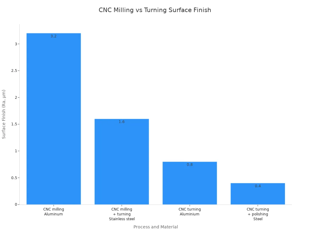
Both forms of cnc machining achieve a tolerance of ±0.0002" with appropriate shop conditions, materials, and setup. However, surface finishes vary across different materials and methods during each cnc turning process. CNC milling on aluminum achieves a surface finish of 3.2 µm Ra. Standard cnc turning on aluminum produces a smooth surface finish of 0.8 µm Ra. A combined CNC milling and turning process on stainless steel yields 1.6 µm Ra. Advanced cnc turning with polishing on steel achieves 0.4 µm Ra. You gain high accuracy, excellent roundness, and great repeatability from this reliable automated process.
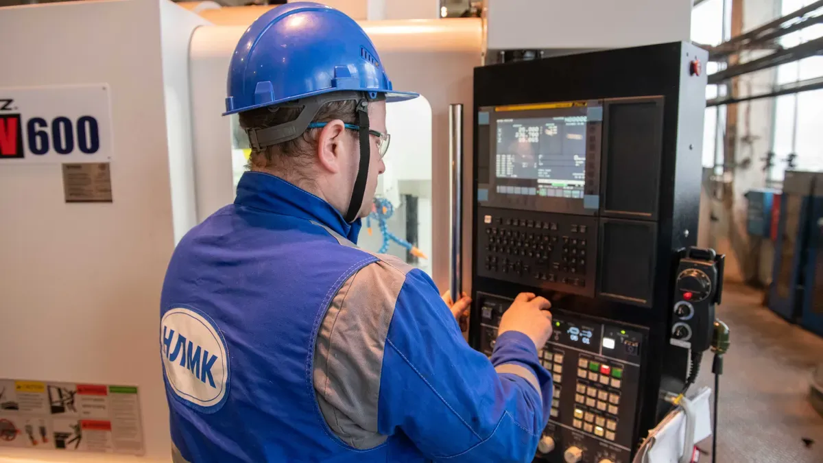
The headstock sits at the front of a standard cnc turning machine. It houses the primary drive motor and the spindle assembly. You rely on the headstock to power the rotational movement of your workpiece. The spindle drives a workholding device like a chuck or collet to grip raw stock firmly. A drawbar secures the chuck onto the spindle by tightening internal springs. This mechanism prevents the workholding unit from loosening during high-speed cnc turning.
Choosing the proper workholding system directly impacts your turning precision. Hydraulic power chucks provide 20-60 kN clamping force for general shop applications.
Workholding Type | Typical Runout | Common Application |
|---|---|---|
Three-jaw chuck | 0.05-0.15 mm TIR | General-purpose cnc turning across wide diameter ranges |
Collet chuck | 0.005-0.01 mm TIR | Precision small-diameter work needing low runout |
Spindle nose designs follow standard styles such as A2-5, A2-6, or A2-8. Selecting a larger spindle nose lets you mount larger, stiffer chucks on metal turning lathes.
The tool turret acts as the primary operational station on a modern cnc lathe. You load cutting tools into indexable positions across the turret body. A standard turret features a 12-station layout, while larger configurations provide a 16-tool capacity. The cnc system automatically rotates the required tool bit into position for precise turning cycles. Driven tools on an advanced cnc turning center allow you to perform milling, drilling, and tapping without moving the part to another lathe unit in your cnc shop.
The tailstock mounts opposite the headstock along the rigid lathe bed. You use this component to support long or slender workpieces against heavy cutting forces during turning operations.
The tailstock quill holds a Morse taper to mount live centers or auxiliary drill chucks.
Hydraulic force extends the quill to clamp against the end face of your workpiece.
This support reduces shaft deflection and minimizes chatter during automated operations on industrial cnc turning machines.
However, tailstock bodies prevent face turning because the physical housing blocks front-facing tool access.
You begin the lathe machining workflow inside digital computer-aided design software. First, you import part designs into software using standard file formats like STEP or DXF. Next, you define your stock diameter, choose cutting tools, and select feeds and speeds. You generate toolpaths for roughing, finishing, and threading inside the program job tree. You run a virtual simulation to check for collisions or gouges before creating NC code through a machine post processor. You review the G-code structure before sending files directly to your equipment. Finally, you transfer the program to your lathe controller through a DNC network interface.
Category | Commands | Turning Workflow Relevance |
|---|---|---|
Motion | G00, G01, G02/G03 | Rapid move, linear cut, and circular arc |
Turning cycles | G33, G71 | Thread cutting and roughing cycle |
Spindle control | M03, M05 | Spindle forward start and spindle stop |
Coolant | M08, M09 | Coolant on and coolant off |
Program flow | M00, M30 | Program stop and program end |

Preparing physical equipment on your lathe machine requires systematic setup steps before starting automated cuts.
Level the lathe machine on a flat surface to maintain high cutting accuracy.
Mount your stock material securely inside the chuck or collet chuck.
Load tool bits into designated turret positions for turning or facing operations.
Set initial spindle speed and feed rate values based on workpiece material properties.
Verify full enclosure safety doors and put on ANSI Z87.1 safety glasses.
Apply cutting fluid or coolant to reduce friction and heat accumulation.
Execute your program at a slow feed rate to verify initial tool paths safely.
Safe operation requires strict workplace safety practices during each cnc turning process. You must inspect interlocked enclosure doors before starting spindle movement. Interlock switches must prevent door opening during rotation to maintain safety compliance under OSHA 29 CFR 1910.212 and ANSI B11.22 standards. You must check transparent viewing panels for scratches and replace damaged windows promptly. You wear cut-resistant gloves when removing chips from the lathe bed, but never wear gloves near spinning spindles. Daily operator maintenance includes verifying fluid levels, checking for hydraulic leaks, and confirming chuck clamping force. You perform periodic geometric calibration using dial indicators to measure spindle runout and axis alignment accurately.
During automated turning execution, dynamic sensors monitor cutting parameters constantly. Adaptive control systems in a modern cnc lathe analyze real-time feedback from tool load sensors. When cutting forces rise or chatter occurs, the system automatically adjusts feed rates to prevent tool overload. Spindle speeds also adjust dynamically to offset material hardness changes and thermal expansion. You manage cut depth indirectly through feed rate adjustments, maintaining target surface quality across every automated lathe machining cycle. Proper operation of a lathe machine protects your cutting tools and ensures consistent part accuracy throughout the whole cnc turning process.
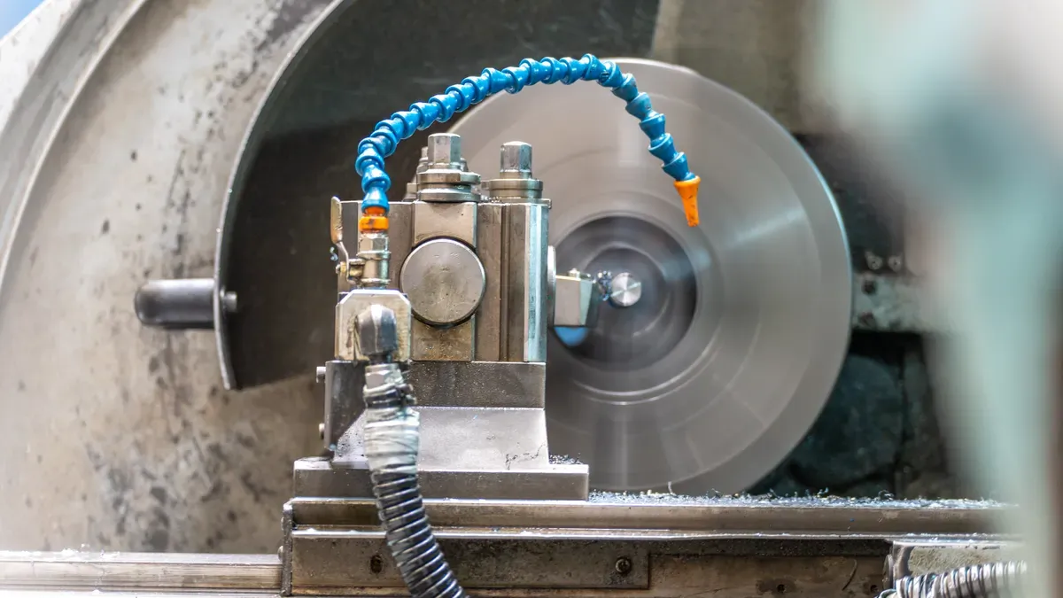
You rely on facing and straight turning as fundamental turning operations in metal fabrication. Straight turning guides a single-point cutting tool parallel to the rotating part axis. This feeding action shaves thin layers off the outer diameter to generate a smooth cylinder. Rough cuts remove stock quickly, while finish cuts achieve accurate diameters and smooth surface finishes. You perform these core cnc turning operations to build reliable cylindrical components.
Facing sets the precise final length of your workpiece perpendicular to the rotation axis. The tool moves radially across the end face, removing a thin layer of material. This operation produces a flat surface that serves as an accurate reference for future setup steps. You can improve facing stability by choosing a 75° entering angle with a square insert to reduce cutting tool deflection.
Aspect | Facing | Straight Turning |
|---|---|---|
Tool direction | Perpendicular to workpiece axis | Parallel to workpiece axis |
Primary goal | Smooth end face and final length | Accurate outer diameter and cylinder |
Tool setup | 75° entering angle for cutting stability | 91–95° entering angle for shoulder clearance |
Selective material removal creates specialized internal and external features during turning machining. Grooving cuts narrow recesses or channels into outer or inner cylindrical surfaces. You program a G75 canned cycle into your controller to execute automated grooving passes efficiently. Threading cuts helical grooves along your workpiece to form precise external screws or internal threaded holes. You use a G76 or G92 canned cycle to synchronize spindle rotation with Z-axis feed motion accurately.
You can apply other specialized methods in basic cnc turning. Tapered turning alters outer diameters along part length to generate conical features. Spherical generation turning crafts smooth rounded shapes using specialized CNC lathe toolpaths. Hard turning machines tough materials rated above 45 on the Rockwell Scale directly. Combining these machine turning operations gives you total control over the entire turning process. This structured process produces consistent parts across every single manufacturing run.
You choose raw materials based on mechanical strength, part weight, and underlying material machinability. Aluminum offers high speed cutting between 122–305 MPM, making it ideal for high-volume parts. Brass cuts cleanly at 90–210 MPM, while free-cutting steels machine well at 35–69 MPM. Stainless steel requires slower cutting speeds between 23–40 MPM to avoid excessive heat buildup and tool wear. Skilled machine shops rely on cnc turning services to shape these metal parts into accurate cylindrical shapes quickly.
Engineers also machine high-performance engineering plastics like PEEK, PTFE, and UHMW on modern metal turning lathes. Plastics can expand up to 20 times more than metal stock during standard cnc machining cycles. Therefore, machine operators use sharp carbide tooling, positive geometries, and proper coolants to reduce localized overheating. Using specialized cnc turning services helps you control thermal deflection and stress cracking on soft plastic workpieces during high-speed production runs.
Many major industrial sectors utilize precision components created through automated turning operations. The global automotive sector represented an exact 33.50% share of the precision turned product market in 2024. Machinists produce transmission shafts, brake drums, and electric vehicle motor pins using advanced cnc turning techniques. U.S. manufacturers reliance on domestic supply reached 83% in aerospace and 76% in automotive during 2022. You can order custom shaft prototypes by connecting with reliable cnc turning services.
Medical device manufacturing relies heavily on turned parts for orthopedic implants, joint stems, and bone screws. In fact, U.S. medical supply penetration reached 69% for domestic precision component production in 2022. Professional cnc turning services deliver micro-scale tolerances on biocompatible titanium stems and surgical connectors. Furthermore, high-speed cnc machining processes quickly manufacture hard-drive shafts and valve stems for electronics and energy equipment. Contract facilities provide specialized cnc turning services to meet rigid quality standards across every production lot.
CNC turning plays a foundational role in modern manufacturing. You shave stock off a rotating workpiece to produce cylindrical components. Mastering lathe mechanics and practical operational steps prepares you for advanced machining topics. This knowledge eases your transition into multi-axis cnc machining.
Understanding these concepts helps you evaluate commercial cnc turning services efficiently. Skilled shops rely on automated equipment for precision turning tasks. Now, practice creating models in CAD/CAM software. You can study basic setups on a manual lathe machine. Operating a physical lathe machine builds true confidence during live cutting. Partnering with certified cnc turning services ensures high quality for complex designs. Direct hands-on practice with basic cnc machining tools sparks growth.
In CNC turning, your workpiece rotates against a stationary cutting tool. In CNC milling, a rotating cutter moves across a fixed workpiece. You use turning to machine round, cylindrical features. You choose milling to create flat faces, pockets, and complex 3D shapes.
You must follow OSHA 29 CFR 1910.212 and ANSI B11.22 safety standards during operation. Always verify interlocked safety doors before starting spindle rotation. Wear ANSI Z87.1 safety glasses during cutting cycles. Put on cut-resistant gloves when clearing chips, but never wear gloves near spinning spindles.
You calculate spindle RPM using the formula: RPM = (Cutting Speed × 1000) / (π × Workpiece Diameter). Enter your cutting speed in meters per minute and your workpiece diameter in millimeters. This calculation establishes the correct velocity for your cutting tool and material combination.
You can achieve tight machining tolerances down to ±0.0002" with proper machine setup and steady shop conditions. Standard turning on aluminum achieves a surface finish of 0.8 µm Ra. Advanced turning with secondary polishing on steel yields an even smoother surface finish of 0.4 µm Ra.


