Email: admin@yeeshine-tech.com WhatsApp: +86-13712868936

- All
- Product Name
- Product Keyword
- Product Model
- Product Summary
- Product Description
- Multi Field Search

Views: 0 Author: Site Editor Publish Time: 2026-10-22 Origin: Site


Imagine realizing a critical clearance issue on a custom pump housing only after investing $50,000 and eight weeks into cutting a steel injection mold. In today's aggressive industrial market, scenarios like this dictate whether a hardware project thrives or falls drastically behind competing innovations. Getting a physical product into your hands quickly is no longer a luxury. It is an absolute necessity. Engineers and product managers simply cannot afford to wait months to verify a complex design concept.
Traditional manufacturing methods require significant upfront capital and rigid timelines. This makes them entirely unsuited for early-stage mechanical testing. Product development teams desperately need a reliable method to validate geometries, test material properties, and confirm fitment without committing to unalterable hard tooling.
The objective solution to this engineering bottleneck is rapid prototyping. By leveraging advanced digital fabrication technologies, companies can bypass traditional tooling phases entirely during the initial stages of development. This comprehensive guide breaks down the mechanics behind the technology, evaluates top methods like subtractive milling and additive printing, outlines material selection criteria, and reveals how to seamlessly transition from an initial concept into scalable manufacturing.
At its core, this practice is a specialized workflow. It translates a digital 3D model into a tangible physical object in a fraction of the time required by conventional mass-production techniques. Instead of spending weeks machining steel molds or configuring complex stamping dies, manufacturers utilize additive layer-by-layer deposition or subtractive precision cutting technologies to create parts directly from a digital file. Consequently, physical parts can be produced and shipped to an engineer's desk in as little as 24 to 48 hours.
Beyond mere visual representation, the primary advantage lies in severe risk mitigation. By holding a physical iteration early in the design cycle, hardware teams can physically test snap-fits on electronic enclosures, evaluate structural integrity under load for brackets, or detect ergonomic awkwardness before committing to mass manufacturing. Furthermore, it aggressively accelerates time-to-market. Cost-effective iteration allows teams to test multiple variations of a single fluid impeller geometry simultaneously. Ultimately, presenting a tangible model significantly improves stakeholder communication. It provides investors with a concrete proof-of-concept rather than relying on idealized digital renderings.
The entire workflow hinges on a clean and manufacturable digital design. Engineers utilize Computer-Aided Design software to build a highly accurate 3D representation of the component. Because the final output's quality is inextricably linked to the precision of this file, strict attention must be paid to critical dimensions, wall thicknesses, and overall geometric stability. Files are typically exported in universal formats like STEP or IGES to ensure seamless translation.
Once the geometry is locked in, the CAD file is translated into machine-readable instructions. For additive technologies, specialized software slices the model into thousands of microscopic horizontal layers. Conversely, for subtractive methods, engineers employ Computer-Aided Manufacturing software to generate precise G-code toolpaths. These toolpaths dictate exactly how the cutting tools will maneuver around the raw material block to achieve the desired tolerances.
This is the physical creation phase where the digital data becomes reality. Depending on the selected technology, automated equipment will either fuse material layer by layer, carve the geometry out of a solid billet, or cure liquid resin using concentrated UV lasers. Procuring a high-quality manufacturing prototype during this stage is essential. The machine operates autonomously based on the digital instructions to yield the physical component with exact specifications.
Raw parts straight off the machine bed rarely reflect the intended consumer product. Comprehensive post-processing is almost always required to achieve the necessary surface finish and specific mechanical properties. This secondary phase can involve manually removing support structures, bead blasting for a uniform matte texture, hand-sanding to achieve a smooth Ra 0.8 finish, anodizing for corrosion resistance, or applying specialized clear coats.
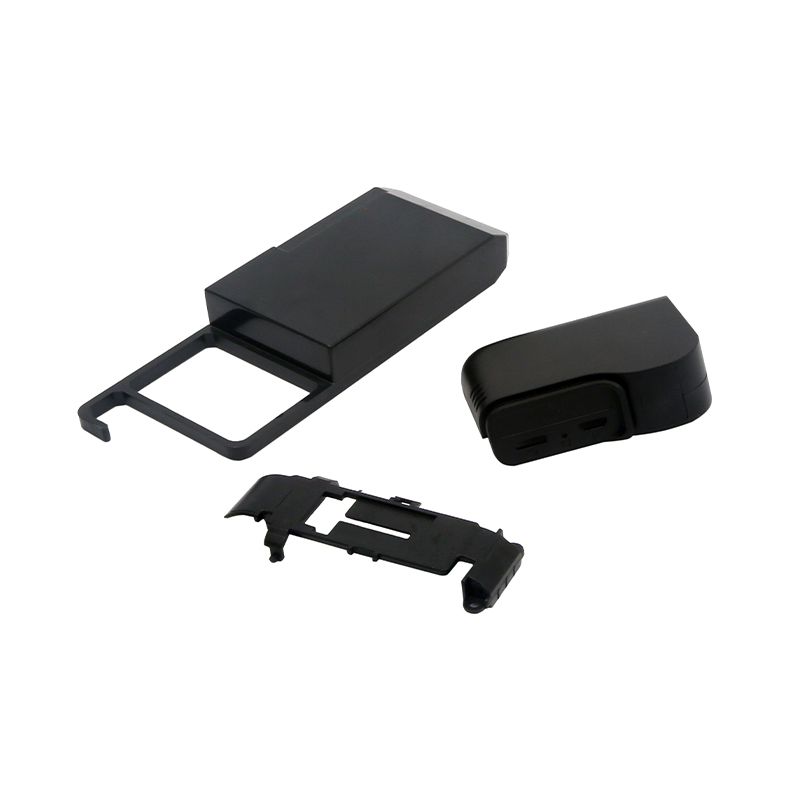
Selecting the correct fabrication technology is the most pivotal decision for achieving your specific testing objectives. Below is an objective breakdown of the primary techniques utilized in modern hardware development, designed to help you match your engineering constraints with the right tool.
| Manufacturing Method | Best Application | Typical Tolerances | Surface Finish | Relative Cost |
|---|---|---|---|---|
| CNC Machining | Functional testing, tight-tolerance mating parts, metal components. | Up to ±0.01mm | Excellent down to Ra 0.8 | Medium to High |
| 3D Printing FDM or SLA | Initial form-factor checks, complex internal geometries, aesthetic models. | ±0.1mm to ±0.2mm | Visible layer lines without sanding | Low |
| Vacuum Casting | Small batches 10-50 units simulating injection molded plastics. | ±0.15mm | Matches master pattern finish | Medium |
| Rapid Sheet Metal | Enclosures, structural chassis, custom mounting brackets. | ±0.1mm | Smooth, ready for powder coat | Low to Medium |
Subtractive manufacturing utilizes high-speed multi-axis cutting tools to meticulously remove material from a solid block of metal or plastic. A machined CNC prototype is the absolute ideal choice when your project demands high precision, incredibly tight tolerances often up to ±0.01mm, and superior surface finishes. Because it utilizes real engineering-grade raw materials, this is the preferred route for creating functional parts that must survive rigorous mechanical stress, chemical exposure, and thermal testing. For instance, testing an O-ring seal on a fluid manifold requires the precise surface finish that only machining can provide.
Additive manufacturing remains the go-to solution for generating complex internal geometries that are simply impossible to machine. Fused Deposition Modeling extrudes thermoplastic filaments, making it excellent for low-cost rapid structural checks. Stereolithography cures liquid resin with a UV laser, resulting in highly detailed and exceptionally smooth models perfect for aesthetic evaluations. Selective Laser Sintering fuses nylon powder with a thermal laser, producing robust and highly functional parts without the need for intrusive support structures.
When you need a small batch of parts that perfectly mimic the material properties of injection molding, vacuum casting is unmatched. A master pattern is first 3D printed or CNC machined. Liquid silicone is then poured around it to form a flexible mold. Once cured, specialized polyurethane resins are injected into the mold under a vacuum. This technique is highly cost-effective for bridging the gap before hard tooling is cut.
For electronic enclosures, mounting brackets, and structural chassis, rapid sheet metal processes involve laser cutting, precision bending, and punching flat metal stock. Validating these structural components early is critical before committing to expensive permanent stamping dies.
The integrity of your testing phase relies entirely on selecting a raw material that closely mirrors your final production intent. A flawless design will still fail if tested using the wrong substrate. Hardware teams must constantly balance material costs against their specific testing parameters.
When developing a plastic prototype, engineers must clearly define whether the part will undergo aesthetic review or harsh functional testing. Common thermoplastics include ABS for excellent general impact resistance, Polycarbonate for high clarity and extreme toughness, and Nylon for superior wear resistance and flexibility. POM or Delrin features exceptionally low friction, making it ideal for moving gears and sliding mechanisms. While standard SLA resins are sufficient for purely visual mock-ups, testing active snap-fits requires resilient engineered thermoplastics.
Functional and load-bearing scenarios typically demand metal. Aluminum 6061-T6 is the industry standard due to its excellent machinability, high strength-to-weight ratio, and relative affordability. For highly corrosive environments or medical device applications, Stainless Steel 304 or 316L is mandatory. In contrast, Titanium is reserved for aerospace and biomedical applications where extreme structural integrity and minimal weight are non-negotiable.
Optimizing your CAD files specifically for your chosen fabrication process can drastically reduce both lead times and manufacturing overhead. Consider these practical engineering strategies to streamline your workflow.
First, implement Design for Manufacturability principles from day one. Designing an intricate internal cooling channel that can only be 3D printed will cause a massive redesign headache if the final part ultimately requires injection molding. Always consider draft angles, tool access, and uniform wall thicknesses early in the CAD phase.
Second, keep tolerances loose wherever possible. Over-tolerancing every single dimension on an engineering drawing exponentially increases machining time, tool wear, and inspection costs. Only apply tight tolerances to critical mating surfaces, bearing fits, and sealing grooves.
Specifically, remember to hollow out thick bulky parts when utilizing additive manufacturing. Solid blocks of plastic take significantly longer to print, consume excess material, and are highly prone to thermal warping. Shelling your parts mitigates all these issues.
When programming subtractive jobs, stick to standard metric or imperial drill and tap sizes. Forcing a machinist to source a custom cutting tool will immediately inflate your quote and delay your shipping date. Furthermore, prototype in iterative stages. Start cheaply by using FDM printing for the first rough dimensional check. Only move to high-fidelity five-axis machining once the core geometry is definitively locked in.
The modern fabrication workflow is no longer an isolated dead-end phase. It naturally and seamlessly evolves into low volume production, typically defined as production runs ranging from 50 to 1,000 units. As consumer product lifecycles continue to compress, forward-thinking companies are utilizing advanced rapid technologies to manufacture end-use parts directly, entirely bypassing the need for mass-production steel tooling.
Moving directly into smaller batch manufacturing allows innovative companies to conduct real-world market testing and fulfill initial crowdfunding orders without risking hundreds of thousands of dollars on injection molds. This strategy drastically minimizes inventory overhead, reduces warehouse costs, and allows for highly agile design modifications based on early real-world user feedback.
Transitioning from a single unit to a run of five hundred requires slight but calculated design adaptations. A complex geometry optimized perfectly for a single SLS print may need uniform wall thicknesses and specific draft angles incorporated to accommodate rapid aluminum tooling or urethane casting. Collaborating with a manufacturer who deeply understands this scaling transition ensures your design remains economically viable as production volumes increase.
Recent market shifts indicate that the rapid fabrication sector is undergoing a massive paradigm shift. Driven largely by global supply chain vulnerabilities over the past few years, the industry is seeing a massive push toward localized on-demand manufacturing. Rather than relying solely on overseas mass production with long shipping delays, Original Equipment Manufacturers are increasingly leveraging industrial-grade additive manufacturing and automated machining to build highly resilient micro-factories closer to the end consumer.
Artificial intelligence is also aggressively accelerating the initial engineering phase. Advanced AI algorithms and digital twin technologies can now analyze complex CAD models in real-time. These systems automatically identify potential manufacturing defects, suggest structural weight-saving optimizations, and predict thermal warping long before a single ounce of material is cut. This AI-driven Design for Manufacturability approach is drastically reducing the trial-and-error phase that historically plagued hardware development.
In addition, the industry is currently experiencing a surge in composite material development. Technologies like continuous carbon-fiber-reinforced 3D printing offer the tensile strength of machined aluminum at a fraction of the weight. Modern smart factories are heavily integrating automated robotic loading systems and pallet changers. This hyper-automation is making subtractive milling faster to set up and far more cost-effective than ever before, successfully narrowing the historical price gap between subtractive and additive methodologies.
A truly reliable manufacturing partner should offer a comprehensive and diverse suite of services under one roof. This includes multi-axis milling, industrial 3D printing, sheet metal fabrication, and vacuum casting. This breadth of capability ensures you receive unbiased technology recommendations tailored specifically to your project's unique needs, rather than a vendor trying to force your design into the only machine they happen to own.
High precision requires rigorous and documented verification. Ensure your chosen facility holds relevant updated ISO certifications, such as ISO 9001, and routinely provides comprehensive inspection reports. Access to Coordinate Measuring Machine data guarantees that the physical part arriving at your desk matches your digital specifications down to the micron.
Ultimately, the most valuable asset a modern manufacturer provides is proactive engineering feedback. A partner who conducts a thorough human-led Design for Manufacturability analysis and clearly communicates potential machining issues before fabrication begins will save your engineering team countless hours and significant financial resources.
3D printing is strictly an additive manufacturing process and represents just one specific tool within the broader industry. Rapid prototyping is the overarching concept and workflow used to quickly create physical models from digital data. While this umbrella term certainly includes 3D printing, it also heavily encompasses subtractive methods like CNC machining, as well as formative methods like vacuum casting and rapid sheet metal fabrication.
Costs are entirely dependent on the chosen fabrication method, the raw material, and the overall geometric complexity of the CAD file. A basic non-functional structural model produced via FDM 3D printing can cost as little as $50. In stark contrast, a highly complex multi-part assembly meticulously machined from aerospace-grade titanium with strict verified tolerances can easily cost several hundred to several thousand dollars.
For most standard non-load-bearing geometries, additive manufacturing methods like SLA or FDM 3D printing are the fastest options available. Because these machines require zero custom toolpath programming and minimal physical setup time, basic plastic models can often be printed, cleaned, and shipped within 24 hours of uploading a file.
Yes, absolutely. While cheap 3D printing filaments like standard PLA are mostly reserved for visual form checks, methods like CNC machining engineering-grade plastics such as PEEK, Delrin, or Glass-filled Nylon produce incredibly durable parts. Furthermore, vacuum casting can utilize specialized polyurethane resins explicitly designed to replicate the exact tensile strength, flexural modulus, and thermal resistance of production-grade injection-molded plastics. This makes them highly suitable for rigorous real-world mechanical testing.
The primary limitation is that prototype materials and processes do not always perfectly match final mass-production properties. For example, a 3D-printed part will have anisotropic properties—meaning it is weaker along the Z-axis—unlike an injection-molded part which is isotropic. Additionally, while prototyping is cost-effective for 1 to 50 parts, the per-unit cost remains too high for scaling into the tens of thousands without transitioning to hard tooling.
The choice comes down to tolerances, material properties, and geometry. If your design features complex internal channels, organic shapes, or requires rapid low-cost iteration, 3D printing is the right choice. However, if your part requires exact mechanical properties, tight mating tolerances below ±0.05mm, superior surface finishes, or uses specific metals like Aluminum or Stainless Steel, CNC machining is the mandatory path.
Agile hardware development forms the absolute backbone of successful modern engineering, empowering companies to iterate rapidly, test thoroughly, and fail cheaply. Whether you require a single conceptual mock-up or are actively scaling into small series plastic CNC machining parts for market production, the integrity of your final product is deeply tied to the expertise of your manufacturing partner. To ensure your custom components meet the strictest industry standards, explore the advanced manufacturing capabilities at Yeeshine Technology. Upload your CAD files today to receive a comprehensive DFM analysis and an instant quote on your next major design project.


