Email: admin@yeeshine-tech.com WhatsApp: +86-13712868936

- All
- Product Name
- Product Keyword
- Product Model
- Product Summary
- Product Description
- Multi Field Search

Views: 0 Author: Site Editor Publish Time: 2026-10-20 Origin: Site


Pick up a complex plastic casing and examine it closely. Run your thumb across the edge. You are likely feeling the physical history of its manufacturing. Whether you are a mechanical engineer reverse-engineering a competitor device, a quality control specialist inspecting an incoming batch, or a procurement manager planning your next project, identifying the exact production method is a crucial professional skill.
This thermal and mechanical process stands as the dominant manufacturing method for mass-producing everything from simple bottle caps to intricate automotive dashboards and life-saving medical devices. The physical mechanics of the tooling always leave behind distinct fingerprints. By knowing exactly what to look for, you can objectively deduce a product origin and evaluate its structural integrity.
To accurately diagnose how a product was made, you must understand the physics of the machinery. The procedure begins with raw thermoplastic pellets fed into a heated barrel. A reciprocating screw melts the polymer through immense shear force and heat until it reaches a specific flowable viscosity.
Once molten, the plastic is injected under extreme pressure. We are talking about forces often exceeding 15,000 PSI. The material forces its way into a precisely machined metal cavity. This metal tooling strictly dictates the final shape. The liquid plastic is forced into a split steel or aluminum mold and mechanically pushed out after cooling. Consequently, the physical interaction between the polymer and the metal leaves permanent traits on the surface.
Understanding these physical interactions is the key to identifying injection molded parts. The tooling mechanics cannot be entirely hidden. Every component carries the physical evidence of its creation.
When inspecting a plastic component, industry professionals look for specific artifacts left behind by the machinery. Grab your part, hold it under a bright inspection light, and look for these primary visual indicators.
This is the exact location where the pressurized molten plastic entered the cavity. The plastic must flow from the machine runner system into the actual part. A physical connection exists during the molding cycle. Once the plastic solidifies, this connection is sheared off, leaving a distinct gate mark.
Depending on the specific tooling design, this mark can appear as a small dimple, a tiny raised bump, or a slightly rough circular patch. Manufacturers typically design molds to place this injection point in non-cosmetic areas. You will often find it on the bottom of a casing or the internal face of a structural component. In high-end consumer electronics, this area may be CNC-trimmed. However, a subtle textural difference usually remains visible if you tilt the part against the light.
Molds are constructed in at least two halves, commonly referred to as the A-side cavity and the B-side core. Therefore, a physical boundary always exists where these two metal plates meet. When the machine clamps shut under high tonnage, a microscopic gap still remains.
During injection, the expanding plastic fills the cavity and presses against this boundary. This creates a faint, continuous seam running along the perimeter or widest cross-section of the part. Run your thumbnail vertically across the edge of a power tool housing. You will likely feel a microscopic ridge catching your nail. The presence of this parting line is a definitive indicator of a split-mold manufacturing process.
After the molten resin has cooled and solidified, the steel mold opens. The plastic naturally shrinks as it cools. This shrinkage causes it to grip the core half of the tooling tightly. To remove the part without warping or snapping it, the machine uses a series of metal rods to physically push the plastic off the metal.
These ejector pins leave behind distinct visual evidence. You will see faint, shallow, circular depressions on the surface of the plastic. They typically range from 2mm to 10mm in diameter. Engineers strategically place these pins on the non-cosmetic, internal sides of the product. They are often located near structural ribs or deep corners where the plastic requires the most mechanical force to be dislodged.
In plastic engineering, vertical walls are rarely perfectly perpendicular to the base. If a part featured exact 90-degree angles, the intense friction generated during ejection would cause severe scraping. It could even lead to structural failure.
To prevent this catastrophic friction, designers incorporate draft angles. This is a slight taper applied to the vertical walls of the part. Typically ranging from 1 to 3 degrees, this taper allows the part to release smoothly from the mold the exact moment ejection begins. Measure the internal walls of a plastic casing with digital calipers. If you notice a slight, intentional taper toward the opening, it is highly probable the item was manufactured using this high-pressure method.
Thick sections of plastic cool significantly slower than thin sections. This temperature variance leads to uneven shrinkage, internal voids, and surface deformations. Consequently, this manufacturing style relies heavily on maintaining a uniform wall thickness throughout the entire design.
To add structural rigidity without thickening the outer walls, designers utilize specific internal features. Look for ribs, which are thin vertical walls that provide bending stiffness. Also, look for bosses, which are cylindrical protrusions designed to receive metal screws or fasteners. The presence of a hollowed-out internal structure supported by a complex network of ribs and bosses is an exclusive hallmark of advanced mold design.
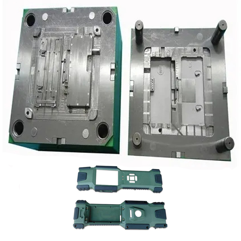
Modern product development frequently requires components with multiple material properties. A common example is a rigid structural polycarbonate body combined with a soft, ergonomic TPU rubberized grip. Cheaper products might have these pieces glued together post-production. Advanced facilities, however, utilize multi-shot processes.
Two-shot molding, commonly known as 2K molding, is a highly sophisticated process. Two different polymers or colors are injected into a single mold during one continuous machine cycle. The first material is injected, the mold rotates, and the second material is injected directly over or adjacent to the first.
To identify this advanced technique, closely examine the boundary between the two materials. In a multi-shot process, the thermal energy of the second injection creates a permanent molecular chemical bond with the first substrate. The transition will be entirely seamless. It will exhibit zero gaps, adhesive residue, or mechanical snap-fits. Unlike parts that are glued together, materials joined through this thermal method cannot be peeled apart without physically tearing the elastomer.
To accurately diagnose a production method, you must rule out other common plastic manufacturing techniques. Comparing their unique visual outputs is the most effective approach.
| Manufacturing Process | Primary Application | Key Visual Indicators |
|---|---|---|
| Injection Molding | Solid, complex, high-volume parts. | Smooth finish, complex internal ribs, mold seams, and circular ejector pin depressions. |
| Blow Molding | Hollow objects, such as bottles and jugs. | A distinct, rough pinch-off scar at the base. Lacks complex internal structures like screw bosses. |
| 3D Printing, including FDM and SLA | Prototypes, low-volume complex parts. | Visible layer lines or support structure removal marks. Parts often feel lighter or less dense. |
| CNC Machining | High-precision, low-volume solid parts. | Microscopic tool marks or swirl patterns from the milling bit. Cannot easily produce sharp internal square corners. |
Identifying the manufacturing process is merely the first step. For procurement professionals and quality control inspectors, analyzing the visual characteristics of a part provides deep insights into the manufacturer competence. This is a highly controlled, pressure-driven thermodynamic process. Any deviation in temperature, tooling design, or machine calibration inevitably manifests as specific physical defects.
Flash and Bleed: This is a thin, unwanted layer of excess plastic that leaks out of the cavity. It typically appears along the mold seam or around ejector pin holes. In a perfectly optimized process, the two halves of the tool are held together by immense clamping pressure. If flash is present, it objectively indicates that the tool is worn out, the machine lacks sufficient clamping force, or the resin viscosity was improperly calibrated.
Sink Marks and Voids: Appearing as shallow craters or localized depressions on the surface, these marks most commonly occur over thick internal sections, such as behind a heavy structural rib. They happen when the inner core of the plastic cools and shrinks slower than the outer skin, pulling the surface inward. This defect points directly to poor thermal management or a failure to adhere to uniform wall thickness guidelines during the design phase.
Short Shots: A short shot occurs when the molten resin freezes before it can completely fill the mold cavity. This results in an incomplete part with missing features or jagged edges. It indicates severe flow restriction. Common culprits include an undersized injection point, inadequate injection pressure, or trapped air inside the tool.
Recent industry analyses reveal a massive global shift toward automated, high-precision manufacturing to mitigate supply chain risks. As sustainability mandates tighten, the industry is rapidly adopting closed-loop recycling systems and bio-based resins. Furthermore, the integration of smart sensors inside the mold cavities now allows for real-time monitoring of melt temperature and cavity pressure, drastically reducing scrap rates.
Despite the rise of AI-driven mold flow analysis and advanced robotics, the fundamental physics of liquid polymer meeting cold steel remain unchanged. Once you know how to identify this process, it becomes abundantly clear why it dominates the consumer goods, automotive, and medical device sectors.
The primary barrier to entry is the tooling cost. Machining a hardened steel mold requires a significant upfront capital investment. However, once the tool is validated, the operational advantages at scale are unparalleled. Cycle times often take mere seconds. A single automated cell can produce thousands of parts per shift. When producing hundreds of thousands of units, the initial tooling cost amortizes rapidly, driving the cost-per-part down to a fraction of a cent.
Recognizing the visual signatures of a molded part ultimately transitions into a critical business decision. Selecting the right supplier for molded plastic components requires looking far beyond their basic press tonnage capacity.
First, evaluate their pre-production engineering support. A superior manufacturer does not simply accept a CAD file and blindly begin cutting steel. They engage in a rigorous Design for Manufacturability review. Utilizing advanced simulation software, their engineers will predict how the resin will flow. They will suggest modifications to optimize draft angles, hide injection points on non-cosmetic surfaces, and prevent sink marks.
Next, assess their tooling standards. Ask if they build to SPI Class 101 standards for high-volume production, ensuring tools can withstand over one million cycles. Verify their technological infrastructure. As product designs become more complex, standard single-shot molding is often insufficient. Determine if the facility possesses advanced capabilities such as insert molding, TPU overmolding onto PC substrates, or multi-shot processing capable of holding tolerances down to ±0.02mm.
Finally, verify their quality management systems. Objective evidence of reliability is found in their certifications. ISO 9001 is the baseline standard for general industrial quality. If you are developing specialized components, look for industry-specific credentials like IATF 16949 for automotive or ISO 13485 for medical devices.
Identifying how a plastic item was manufactured boils down to knowing where to look. By checking for the subtle but permanent physical traits, you can confidently determine the production method used.
Understanding these unique manufacturing fingerprints empowers you to assess product quality accurately. It allows you to reverse-engineer competitor designs and make highly informed decisions for your supply chain. When you know the mechanics behind the plastic, you hold the key to better product development.
If you are ready to transition your next project from prototype to high-volume production, partnering with an experienced manufacturer is critical. Explore the advanced engineering solutions and precision tooling capabilities at Yeeshine to ensure your next batch of components meets the highest global standards.
A mold seam is a normal, unavoidable, and microscopic line on the surface of a part. It marks the exact location where the two halves of the steel tooling meet when closed. Flash, however, is a manufacturing defect. It occurs when excess molten plastic escapes the confines of the cavity and bleeds out along that seam, creating a sharp, unwanted fin of material. While a faint seam is standard, flash indicates a breakdown in process control, such as inadequate clamping pressure or degraded tooling.
They cannot be entirely prevented during the injection process, as the molten plastic must physically enter the cavity through a specific channel. However, experienced engineers strategically place this entry point on the interior or bottom of the part, rendering it invisible to the end-user. If a perfectly smooth surface is absolutely required at the injection site, the mark can be manually trimmed, sanded, or CNC-machined off during post-production, though this will increase overall labor costs.
The most definitive visual difference lies in the surface finish and structural uniformity. 3D printed parts are created through additive manufacturing, depositing material layer by layer. This leaves visible, textured striations across the surface, and the parts often feel lighter due to internal lattice infills. In contrast, molded components are formed under immense pressure in a polished metal cavity. They exhibit a smooth, highly uniform surface finish, feature solid wall structures, and bear distinct mechanical signatures like ejector pin depressions, which are entirely absent in 3D printed objects.
Generally, no. The primary barrier is the capital expenditure required to design, CNC machine, and polish the custom steel or aluminum tooling, which can cost tens of thousands of dollars. For low-volume prototyping, typically fewer than one thousand units, processes like 3D printing or urethane casting are much more cost-effective. However, once production volumes scale into the tens of thousands, the initial tooling cost is amortized across the large number of units, making it the most cost-efficient method available.
Wall thickness dictates the cooling rate of the molten polymer inside the tool. If a part has uneven wall thicknesses, the thicker sections will cool and shrink much slower than the thinner sections. This differential cooling creates internal mechanical stress, leading to severe warping, sink marks, or structural voids. Maintaining a uniform wall thickness is the most critical design rule for ensuring dimensional stability and cosmetic perfection.
Engineers can select from thousands of highly specialized thermoplastics depending on the application. Common commodity resins include Polypropylene and ABS, widely used for consumer goods and electronics housings due to their impact resistance. For demanding engineering applications, materials like Polycarbonate, Nylon blended with glass fibers, and TPU are utilized to provide extreme tensile strength, thermal resistance, and flexible overmolding capabilities.


