Email: admin@yeeshine-tech.com WhatsApp: +86-13712868936

- All
- Product Name
- Product Keyword
- Product Model
- Product Summary
- Product Description
- Multi Field Search

Views: 0 Author: Site Editor Publish Time: 2026-09-26 Origin: Site


Gate design is one of the most important decisions in an injection mold because every gram of molten plastic entering the cavity must pass through the gate. Its size, position, shape, and type influence filling pressure, shear, weld lines, air traps, sink marks, gate vestige, cycle time, and the final appearance of the molded part.
The right choice among different injection molding gate types depends on far more than part size. Engineers need to consider resin behavior, wall thickness, cosmetic surfaces, expected production volume, cavity layout, automatic degating, dimensional requirements, and whether a cold runner or hot runner system is being used.
A gate that performs well on a thick ABS enclosure may be inappropriate for a thin PP container, transparent PC component, glass-filled nylon clip, or soft TPE seal. Gate selection should therefore be treated as part of the complete mold-flow and DFM process rather than an isolated mold detail.
YEESHINE TECHNOLOGY CO., LIMITED provides integrated engineering design, mold manufacturing, and plastic injection molding services for automotive, electronics, medical, household, and other plastic components.
An injection molding gate is the controlled opening between the runner system and the mold cavity. Molten resin travels from the machine nozzle through the sprue and runner before entering the cavity through this relatively small opening.
The gate performs several functions at the same time. It controls the direction and rate at which material enters the part, influences how cavity pressure develops, and eventually freezes to prevent material from flowing back out of the cavity during cooling.
Gate design therefore affects both filling and packing.
A gate that is too small may generate excessive shear, require higher injection pressure, freeze before adequate packing occurs, or cause short shots in long flow paths. A gate that is unnecessarily large may increase gate-removal work, leave a larger vestige, extend gate-freeze time, and make cosmetic finishing more difficult.
Gate location matters just as much as gate size. If melt fronts meet in a mechanically weak or highly visible location, weld lines may become unacceptable. If the gate forces plastic to travel through a thin section before reaching a thick region, packing can become difficult and increase the risk of sink marks or dimensional variation.
YEESHINE's article on optimizing injection mold design also identifies gate and runner layout as key factors affecting melt flow, weld lines, trapped air, shrinkage, and overall molding stability.

The most suitable gate type depends on what the molded component needs to achieve.
Gate Type | Main Advantage | Main Limitation | Typical Application |
|---|---|---|---|
Edge Gate | Simple and versatile | Visible gate mark, usually trimmed | General flat plastic parts |
Fan Gate | Spreads flow across wide area | Larger gate to remove | Wide or thin parts |
Tab Gate | Reduces direct shear into part | Extra tab material | Thin cosmetic parts |
Direct Sprue Gate | Strong flow into thick parts | Large gate vestige | Large or thick single-cavity parts |
Pin Gate | Small gate mark | Higher shear and pressure | Small parts, multi-cavity molds |
Submarine Gate | Automatic degating | More complex machining | High-volume automatic molding |
Cashew/Banana Gate | Hides gate from visible surface | Complex and wear-sensitive | Cosmetic housings |
Diaphragm Gate | Uniform radial filling | Difficult gate removal | Round or cylindrical parts |
Ring Gate | Balanced flow around cylinder | More runner material | Tubular components |
Hot Tip Gate | Low runner waste | Higher mold cost | Cosmetic high-volume parts |
Valve Gate | Precise gate control | Higher system complexity | Large, cosmetic or sequentially filled parts |
This table is a useful starting point, but no gate should be selected only from a generic application description. Mold-flow length, resin viscosity, fiber orientation, wall thickness, and the allowable gate mark can completely change the recommendation.
Edge-type gates are among the most widely used cold-runner gate designs because they are simple to machine, easy to adjust, and compatible with a broad range of thermoplastics.
The gate normally enters the part at the mold parting line, which makes manufacturing and maintenance relatively straightforward.
An edge gate uses a rectangular opening that connects the runner directly to the edge of the component.
It works well for many flat or moderately thick parts and provides a relatively unrestricted flow path compared with very small pinpoint gates. This can make it suitable for ABS, PP, PC/ABS, nylon, and many general engineering resins depending on part design.
The main disadvantage is the visible gate vestige after trimming.
If the gate is located on a cosmetic surface or an edge used for assembly, trimming quality can become an additional manufacturing requirement.
Edge gates are therefore often positioned on hidden surfaces, internal flanges, or areas that will later be covered during assembly.
A fan gate gradually widens before entering the cavity.
Instead of forcing melt through one narrow point, it distributes flow across a larger section of the part. This can reduce localized shear and help fill broad, thin-walled components more uniformly.
Fan gates can be useful for large covers, panels, housings, and parts where a narrow edge gate could produce strong flow lines or uneven orientation.
The trade-off is a wider gate vestige that normally requires trimming.
For highly cosmetic parts, the designer needs enough non-visible edge length to place and remove the gate without damaging the finished appearance.
A tab gate adds a sacrificial section between the runner and the molded component.
The high shear associated with gate entry is concentrated in the tab rather than immediately entering the finished part. This can be useful for materials or designs that are sensitive to stress, jetting, or visible flow disturbances.
After molding, the tab is removed as a secondary operation.
The additional material and trimming are disadvantages, but they can be worthwhile when protecting a sensitive cosmetic or structural area is more important than minimizing runner waste.
Some components benefit from a larger and more symmetrical melt entry rather than a small side gate.
This is particularly true for thick parts, cylindrical components, and products where concentric filling matters.
A direct sprue gate feeds resin almost directly from the machine nozzle and sprue into the cavity.
The large flow area allows molten plastic to enter with relatively low restriction, making this design useful for thick components and some large single-cavity parts.
Because the gate remains relatively large, packing pressure can be maintained for longer before freeze-off. This can help compensate for shrinkage in thick sections.
The disadvantage is an obvious gate mark and greater trimming requirement.
Direct sprue gating is therefore usually selected for parts where gate appearance is less important than reliable filling.
A diaphragm gate introduces plastic around the circumference of a round opening.
Because material enters symmetrically, it can produce more balanced radial flow and help maintain concentricity on cylindrical components.
Typical applications include circular or tubular parts where one-sided gating could create uneven shrinkage or distortion.
The major disadvantage is gate removal. The diaphragm typically needs to be cut away around the entire circumference, creating more finishing work than a small edge or pinpoint gate.
A ring gate uses a similar balanced-flow concept around cylindrical parts.
The objective is to distribute melt more uniformly around the circumference rather than allowing one melt front to dominate.
This can reduce some forms of weld-line imbalance and dimensional variation in tubular components.
Again, additional runner and gate material makes this design less attractive when automatic separation and minimum material waste are major priorities.
High-volume injection molding often benefits from gates that separate automatically when the mold opens or the part is ejected.
Automatic degating reduces manual labor and makes molding cells easier to automate.
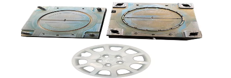
A pin gate, sometimes called a pinpoint gate, uses a small circular gate that commonly separates automatically from the component during mold opening.
Its small gate vestige makes it useful for consumer products and other components where a large edge mark is undesirable.
Pin gates also work well in multi-cavity layouts because runners can feed several cavities through relatively small gate points.
However, reducing gate diameter increases flow restriction.
High injection pressure and shear may become a concern for highly viscous or shear-sensitive materials. The gate can also freeze rapidly, limiting the time available for packing.
For that reason, gate diameter must balance appearance against process stability.
A submarine gate, also called a tunnel gate, approaches the cavity at an angle below the parting line.
As the part ejects, the gate is automatically sheared from the molded component. This makes submarine gating popular in high-volume molds where automatic production is important.
It can also hide the gate on an underside or less visible area.
YEESHINE has used a submarine gate in its TPE seal injection mold project, demonstrating how this gate type can be incorporated into production tooling when geometry and material behavior permit.
Submarine gates require more precise machining than standard edge gates. Gate angle, tunnel length, resin flexibility, gate size, and ejection direction all need careful design.
A tunnel that is too aggressive may cause gate breakage inside the mold or leave an inconsistent vestige. Highly brittle plastics can also be less forgiving during automatic gate separation.
A cashew gate is a curved variation of the submarine-gate concept.
It allows the gate to reach an internal or hidden area that cannot be accessed through a straight tunnel.
This can be very useful for highly cosmetic housings where the visible outer surface cannot tolerate a gate mark.
However, the curved gate insert is more complex to manufacture and maintain.
The design also needs to allow the solidified runner to flex and release reliably during ejection. For this reason, cashew gates should be selected only when the cosmetic benefit justifies the additional tooling complexity.
Hot runner systems keep plastic molten inside heated channels instead of ejecting a cold runner with every molding cycle.
This reduces runner waste and can make high-volume molding more efficient, particularly when expensive engineering plastics or multi-cavity molds are involved.
YEESHINE manufactures molds using both hot and cold runner systems, depending on product precision, production requirements, and mold design.
A hot tip gate delivers resin from the heated runner directly into the mold cavity.
Because there is no conventional cold runner attached to the part, material waste can be reduced substantially.
Hot tip gates can also create relatively small gate vestiges and are commonly used for cosmetic consumer components.
However, mold design becomes more complex.
Temperature control needs to keep resin inside the runner molten without overheating or degrading it. The thermal relationship between nozzle tip, cavity, and gate also influences gate appearance and stringing.
Hot runner systems therefore require greater initial tooling investment than simple cold-runner molds.
A valve gate adds a mechanically controlled pin that opens and closes the gate.
This allows engineers to control exactly when material enters each gate and when the gate closes.
The design is particularly valuable for large parts with multiple gates.
Instead of allowing every gate to fill simultaneously, the molding process can use sequential valve gating. Gates open according to the progress of the melt front, which can help manage weld lines, filling pressure, and cosmetic appearance.
Valve gates can also provide a cleaner gate vestige than some open hot-tip designs.
The disadvantages are higher mold cost, more components, more control requirements, and additional maintenance.
For high-volume or high-value plastic components, those costs can be justified by reduced runner waste and improved process control.
Resin properties have a major influence on gate design.
Viscosity, shear sensitivity, fiber reinforcement, shrinkage, processing temperature, and crystallization behavior all affect how material passes through the gate and fills the cavity.
ABS and PC/ABS are widely used for electronic housings, automotive interior components, and consumer products.
They can work with edge, fan, submarine, pin, and hot runner gates depending on wall thickness and cosmetic requirements.
For an electronic enclosure, the gate is often positioned on a hidden surface while melt flow is directed so that weld lines do not occur around critical bosses, clips, or highly visible areas.
YEESHINE provides electronics injection molding for housings and precision components where appearance, gate location, and dimensional consistency need to be considered together.
PC generally has relatively high melt viscosity.
Extremely small gates can increase injection pressure and shear, making adequate gate size and effective venting important.
For transparent PC components, flow marks, jetting, burn marks, and gate stress can also become highly visible.
The gate should therefore support smooth filling without placing excessive stress near critical transparent or snap-fit regions.
PP and PE generally flow well and can work with many gate configurations.
Submarine and pin gates are often practical for high-volume parts when automatic separation is desired.
However, their relatively high shrinkage means gate location and packing remain important for controlling warpage.
Parts with large flat surfaces can benefit from wider gates that provide more balanced filling.
Nylon materials can flow well, but fiber-reinforced grades introduce another design factor: fiber orientation.
As glass-filled resin passes through the gate, fibers tend to align with the flow direction.
This orientation affects shrinkage, stiffness, weld-line strength, and dimensional behavior.
Gate location should therefore be selected not only to fill the part but also to produce favorable fiber orientation in structurally important regions.
YEESHINE has experience with precision nylon molded components, including automotive-style clips and snap-fit parts, making DFM and flow direction especially important for these geometries.
Soft thermoplastic elastomers require careful gate and ejection design.
Their flexibility can make tunnel-gate separation possible in some designs, but very soft materials may stretch rather than break cleanly if the gate geometry is unsuitable.
Gate size also influences shear heating and cosmetic quality.
For seals and flexible parts, the mold engineer should evaluate resin hardness together with gate geometry rather than treating all TPE grades as identical.
The best gate normally fills from thicker sections toward thinner sections.
This is because thicker regions remain molten longer and can transmit packing pressure deeper into the component.
Gating into a very thin region and forcing melt toward a much thicker boss or structural section can cause the gate to freeze before shrinkage in the thick section has been compensated.
Thin parts require fast, balanced filling before the melt freezes.
Fan or wide edge gates can distribute plastic over a larger flow front and reduce the pressure required to fill a broad surface.
For very small thin parts, pinpoint gates can also work if resin flow is sufficient.
Thicker components often benefit from larger gates that remain open longer during packing.
Direct sprue or larger edge gates may therefore be more appropriate than very small pinpoint gates.
Packing effectiveness becomes particularly important when avoiding internal voids or excessive sink marks.
Parts with long flow lengths may require multiple gates or a gate positioned closer to the geometric center.
Trying to fill a long component from one small gate can cause high injection pressure and incomplete filling.
Mold-flow analysis can help determine whether adding a second gate provides better balance.
However, every additional gate creates another melt-front intersection and potential weld line.
The correct design therefore balances pressure reduction against weld-line location.
Choosing the right gate type does not guarantee a good molded part if the gate is placed incorrectly.
Gate location controls where the first melt enters, how the flow front travels, where air is displaced, where fibers orient, and where separate melt fronts meet.
A strong gate-location review should consider the entire part.
When two melt fronts meet around a hole, boss, insert, or multiple gate locations, a weld line forms.
The weld line may have lower mechanical strength than the surrounding material, particularly with fiber-filled resins.
If possible, it should be moved away from snap hooks, screw bosses, pressure-loaded regions, sealing surfaces, or highly visible areas.
Changing the gate position can often move the weld line without changing the component itself.
The gate pushes air ahead of the melt front.
If the final area to fill does not have adequate venting, trapped air can create burns, incomplete filling, or local surface defects.
Gate position and vent position therefore need to be designed together.
The ideal flow pattern moves air toward deliberate vents rather than into a blind pocket.
Consumer electronics, medical housings, and automotive interior trim can have strict cosmetic requirements.
Gate marks should normally be placed on hidden or non-cosmetic surfaces when possible.
This is one reason submarine, pin, cashew, hot-tip, and valve gates are attractive for high-appearance products.
However, cosmetic requirements should not force a gate into a location that makes the part impossible to fill reliably. Moldability and appearance need to be balanced through DFM.
A significant number of injection molding defects can be influenced by gate type, size, or location.
Defect | Possible Gate-Related Cause |
|---|---|
Short Shot | Gate too small or flow path too long |
Jetting | Melt enters cavity too quickly without contacting mold wall |
Burn Marks | Air trapped at end of fill |
Sink Marks | Gate freezes before adequate packing |
Weld Lines | Poor gate location or multiple unbalanced flow fronts |
Warpage | Unbalanced filling, packing, or fiber orientation |
Gate Blush | Excessive shear near gate |
Gate Vestige | Gate too large or poor degating design |
Stress Cracking | High gate shear or residual stress |
Uneven Dimensions | Unbalanced filling or packing |
These defects should not automatically be solved by changing machine parameters.
Increasing injection pressure may temporarily compensate for an undersized gate, for example, but it can also increase stress and flash elsewhere.
A better troubleshooting process examines part design, gate geometry, runner balance, venting, cooling, and process settings together.
Gate-removal strategy becomes increasingly important as production volume increases.
For a prototype mold producing a few hundred parts, manually trimming an edge gate may be completely acceptable.
For a multi-cavity mold producing millions of components, manual trimming can become a major labor and consistency problem.
Common manually removed gates include edge, fan, tab, direct sprue, diaphragm, and some ring gates.
Their advantages are generally simpler mold construction and easier maintenance.
They are particularly suitable when production volume is moderate or when a larger gate is required for reliable filling.
The disadvantage is downstream labor.
Poor trimming can also leave inconsistent vestiges or damage the finished part.
Submarine, pinpoint, and many hot runner gate systems can separate automatically.
This supports robotic part handling and unattended molding cells.
Automation becomes especially valuable in multi-cavity tooling because every cycle may produce several gate connections that would otherwise need manual removal.
Automatic gating can therefore justify a more expensive mold when production volume is high enough.
The correct decision should compare total manufacturing cost over the expected mold life rather than initial mold price alone.
Gate selection is best made during DFM, before mold steel has been machined.
Changing a gate after tooling has been completed can require welding, machining, new inserts, runner modification, or major hot-runner changes.
Before selecting a gate, engineers should review:
Plastic material
Resin viscosity
Fiber reinforcement
Part dimensions
Wall thickness
Flow length
Cosmetic surfaces
Critical mechanical areas
Weld-line locations
Gate vestige requirements
Number of cavities
Production quantity
Cold or hot runner
Automatic degating requirements
Cycle-time target
Packing requirements
Ejection direction
Mold-flow simulation can provide additional information for complicated components.
It can predict fill pattern, pressure demand, weld-line locations, air traps, temperature distribution, and potential filling imbalance before expensive tooling modifications are required.
YEESHINE TECHNOLOGY CO., LIMITED integrates engineering, mold manufacturing, prototyping, and injection molding, allowing gate design to be reviewed together with the complete part and manufacturing process. Its plastic injection molding parts capabilities cover materials including ABS, PC, POM, PMMA, PP, PA, TPU, TPE, and other engineering plastics.
Tip: When requesting a mold quotation, identify cosmetic surfaces and critical functional areas on the drawing. This helps the mold engineer avoid placing gates and weld lines where they could affect appearance or performance.
Choosing among different injection molding gate types requires balancing moldability, appearance, automation, tooling cost, material behavior, and final part performance.
Edge gates remain a versatile and economical choice for many general plastic parts. Fan and tab gates can help distribute flow or reduce local shear. Direct sprue gates provide strong filling for larger or thicker parts, while diaphragm and ring gates support balanced filling of cylindrical geometries.
Pin and submarine gates are useful when automatic degating and small gate vestiges are priorities. Hot tip and valve gate systems can reduce cold-runner waste and provide greater control in high-volume or cosmetic molding applications.
Gate type alone, however, does not determine molding success. Gate size and location influence filling pressure, fiber orientation, packing, weld lines, air traps, warpage, and cosmetic quality.
The best gate is therefore the one that matches the plastic material, part geometry, surface requirements, expected production volume, and complete mold design.
YEESHINE TECHNOLOGY CO., LIMITED provides injection mold design, mold manufacturing, prototyping, and plastic injection molding for automotive, electronics, medical, household, and other applications. Gate, runner, cooling, venting, and ejection can be evaluated together during DFM to reduce mold modifications and improve production stability.
A: The edge gate is one of the most widely used gate types because it is simple to manufacture, supports many plastic materials, and provides a relatively unrestricted flow path.
A: Pinpoint, submarine, hot-tip, and valve gates can all provide relatively small gate vestiges. The best option depends on the resin, part geometry, mold structure, and cosmetic requirements.
A: A submarine gate, or tunnel gate, enters the cavity below the parting line and is normally designed to separate automatically during part ejection.
A: A fan gate is useful for broad or thin components where melt needs to enter across a wider section to improve flow distribution and reduce localized shear.
A: A cold runner solidifies and is normally ejected with each cycle, while a hot runner keeps plastic molten inside heated channels, reducing runner waste but increasing mold complexity and initial cost.
A: Gate location determines how melt fronts travel through the cavity and where they meet. Moving the gate can therefore relocate weld lines away from mechanically critical or cosmetic areas.
A: Yes. If a gate is too small or freezes too early, sufficient packing pressure may not reach thick areas of the part, increasing the risk of sink marks or internal shrinkage.
A: Yes. Gate type, location, runner design, venting, cooling, and ejection should ideally be reviewed during DFM before mold machining begins.


